
USES
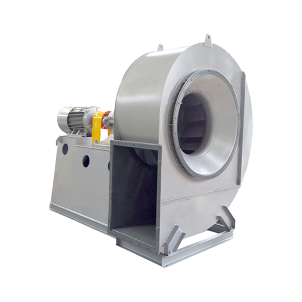
G4-73 and Y4-73 boiler induced draft fans are mainly suitable for induced draft fan systems of 2 to 670 t/h steam boilers in thermal power plants. G4-73 can also be used for mine ventilation and general ventilation when there are no other special requirements. The medium conveyed by the ventilator is air, and the maximum temperature shall not exceed 80℃; the medium conveyed by the induced draft fan is flue gas, and the maximum temperature shall not exceed 250℃. A dust removal device must be installed before the induced draft fan to minimize the dust content of the flue gas entering the fan. According to the use of general power plants, the efficiency of the dust collector shall not be less than 85%.
FORM
1. Both the ventilator and the induced draft fan are made into single suction, each with 13 numbers from 8 to 29.5.
2. When viewed from one end of the motor, the impeller rotating clockwise is called a right-handed fan, represented by “right”; the opposite is a left-handed fan, represented by “left”.
3. The outlet position of the fan is represented by the outlet angle of the casing.
4. The transmission mode of the fan is D-type, and elastic couplings are used for connection.
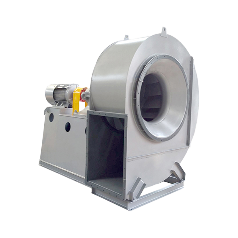
STRUCTURAL FEATURES
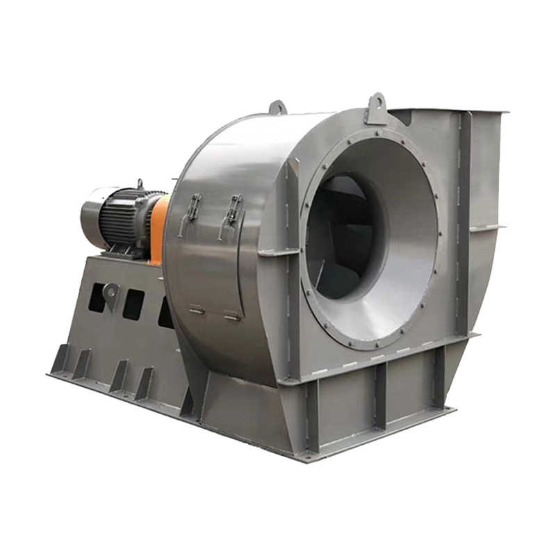
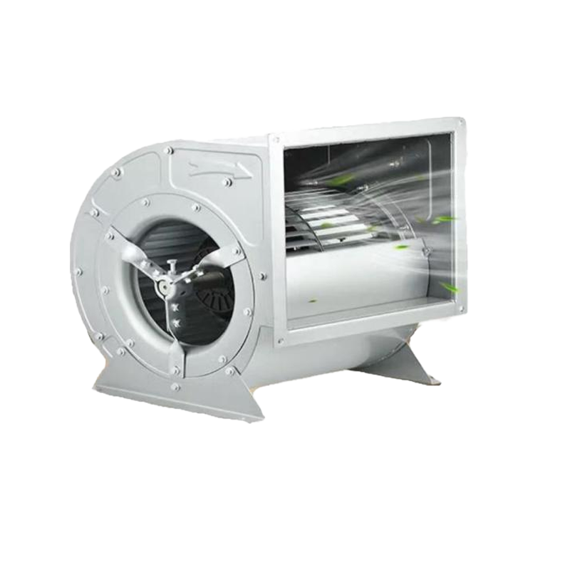
① Impeller – 12 backward-inclined wing-shaped beveled blades are welded between the conical arc front disk and the flat rear disk. The use of wing-shaped blades ensures high efficiency, low noise and high strength of the fan. The impeller has been subjected to static and dynamic balance correction and overspeed operation test, so it runs smoothly and reliably. The impellers of the same machine number for the induced draft fan and the induced draft fan have the same structure but different materials. Generally speaking, A3 is selected for the ventilator and 16Mn is selected for the induced draft fan.
② Casing – Ordinary steel plates are welded into a volute body. The casing of the single-intake fan is made into three different forms (the casing of No. 8 to 12 is made into an integral structure and cannot be disassembled, the casing of No. 14 to 16 is made into a two-open type, and the casing of No. 18 to 29.5 is made into a three-open type). For the induced draft fan, the volute plate is appropriately thickened to prevent wear.
③ Air inlet—The convergent and streamlined air inlet is made into an integral structure and fixed to the side of the fan inlet with bolts.
④ The device used to adjust the flow rate is installed axially in front of the air inlet. The adjustment range is from 0° (fully open) to 90° (fully closed). The handle position of the adjustment door: on the right side from the air inlet direction. For the right-handed fan, the handle is pushed from bottom to top from fully closed to fully open, and for the left-handed fan, the handle is pulled from top to bottom from fully closed to fully open.
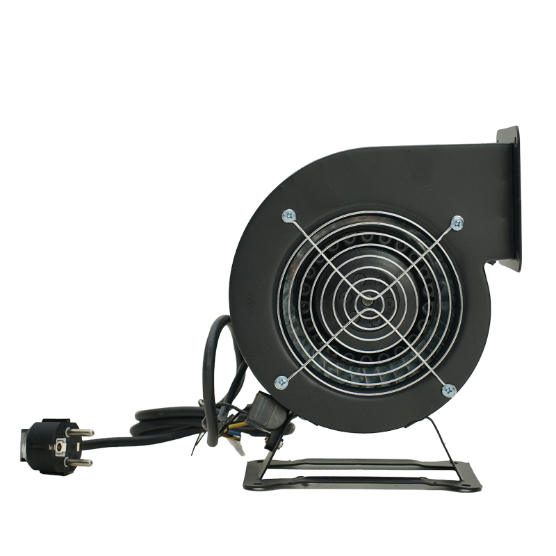
⑤ Transmission group—The main shaft of the transmission part is made of high-quality steel, and this fan uses rolling bearings. There are two types of bearing boxes: №8 ~ 16 use an integral cylindrical bearing box; №18 ~ 29.5 use two independent pillow bearing boxes. The bearing box is equipped with a thermometer and an oil level indicator (only for induced draft fans). The lubricating oil uses No. 30 mechanical oil, and the amount of oil added is based on the oil level mark requirements. №8~16 If the integral barrel bearing box adopts dry oil, an oil baffle plate should be added on the ball side of the bearing box, and its fixing groove has been made. The induced draft fan is equipped with a water cooling device, so a water pipe must be installed. The water consumption varies with the temperature, and is generally considered to be 0.5~1 m³/h.
OPERATION
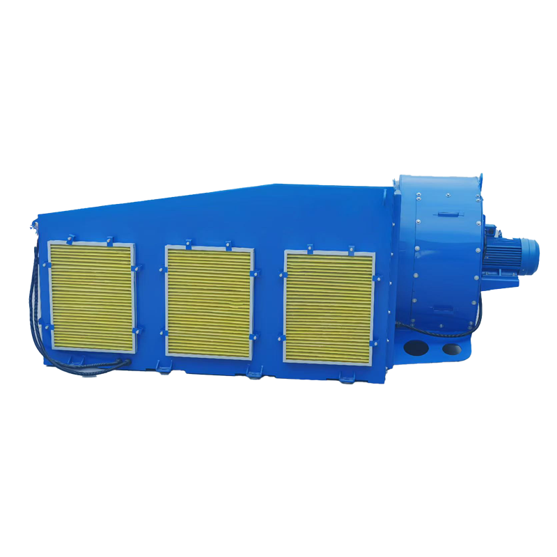
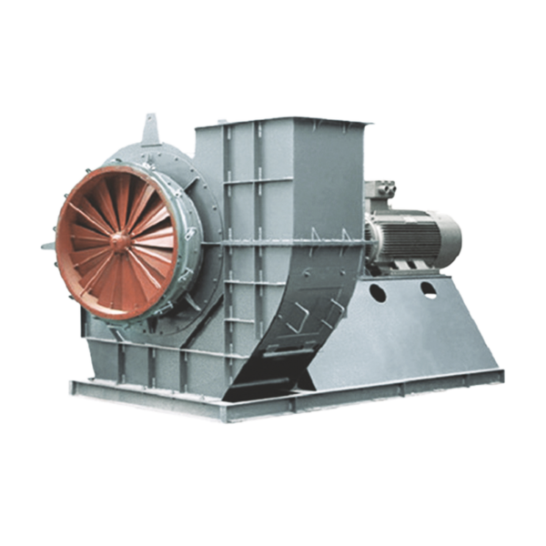
G, Y4-73No20F ~ 31.5F is a induced draft fan for 100,000 and 200,000 kW thermal power generating units.
It is a new product designed based on G, Y4-73Nn20D~29.5D and based on the problems in production and use over 20 years. Compared with the original series of fans, the following major improvements have been made:
① The original fan cantilever support (D type) transmission mode has been changed to the intermediate support (F type) transmission mode, which improves the stability of the fan operation.
② Through the model (impeller outer diameter D=1000 mm) test, the air inlet chamber suitable for this type of fan has been added, and the shape of the original air inlet has been changed to an eccentric air inlet.
③ A wing-shaped blade adjustment door is installed at the inlet of the air inlet chamber to adjust the characteristics of the fan and improve the adjustment efficiency of the fan. The support of the adjustment blade is equipped with a rolling bearing, which is flexible in rotation and reliable in use.
④ Since the operating environment temperature of most blowers is high and the bearings are prone to heat up, the bearing box of the new series of fans is also water-cooled like the induced draft fan.
⑤ The design of the new fan enhances the rigidity of the casing and the air inlet chamber. A grid plate of appropriate height is welded on the outside of the casing and the air inlet chamber, and a hollow tube support is welded inside, thereby eliminating the vibration caused by the insufficient rigidity of the casing.
⑥ Considering the dust particle wear problem of the induced draft fan impeller, the solid part of the wing-shaped blade head is enlarged, and a wear plate is added at the rear disc of the blade. At the same time, a wear-resistant layer is welded with a wear-resistant electrode at the wear-prone part, and the hardness can reach HRC48 or above, which prolongs the service life of the impeller and meets the requirements of power plant use and maintenance.