
Application
Application: This fan is generally used for high-pressure forced ventilation (delivery) or pneumatic conveying of materials in metallurgy, petroleum, chemical industry, grain, building materials industry and other departments. It is suitable for conveying air and non-corrosive, non-explosive, non-spontaneous combustion, and non-viscous gas. The temperature of the medium is generally not more than 50″C (maximum not more than 80°C), and the dust and hard fine particles contained in the medium are not more than 150mg/m³.
TYPE
1. The fan is made of single suction, and the machine numbers are No.8a, 8, 8b, 8.5a, 8.5, 8.5b, 9a, 9, 9b, a total of nine types.
2. The fan can be made into two types of clockwise rotation or counterclockwise rotation. Looking at the fan from the transmission part, if the impeller rotates clockwise, it is called a clockwise rotating fan, represented by “clockwise”; if it rotates counterclockwise, it is called a counterclockwise rotating fan, represented by “counterclockwise”.
3. The outlet position of the fan is represented by the outlet angle of the casing. “Clockwise” and “counterclockwise” can be made into three angles of 0°, 90°, and 180°.
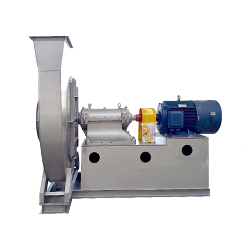
4) The transmission method of the fan adopts D-type coupling direct drive.
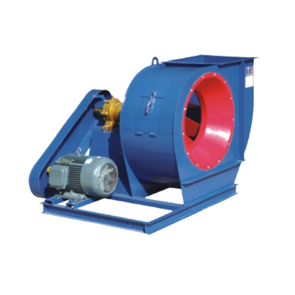
STRUCTURE FEATURES STRUCTURAL FEATURES
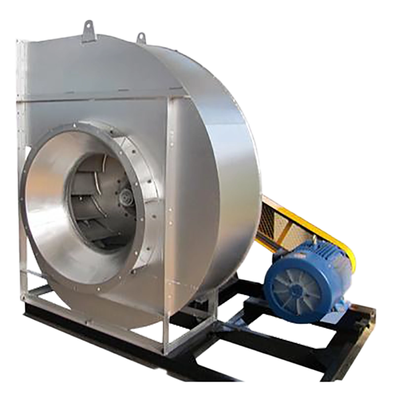
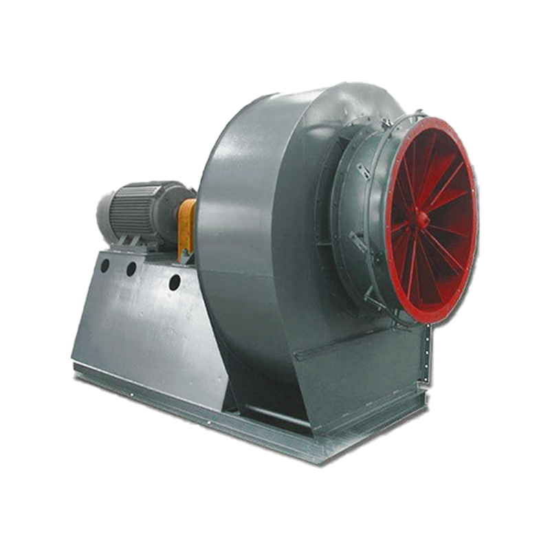
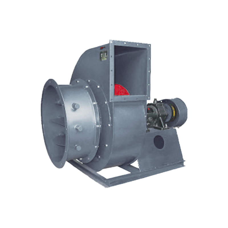
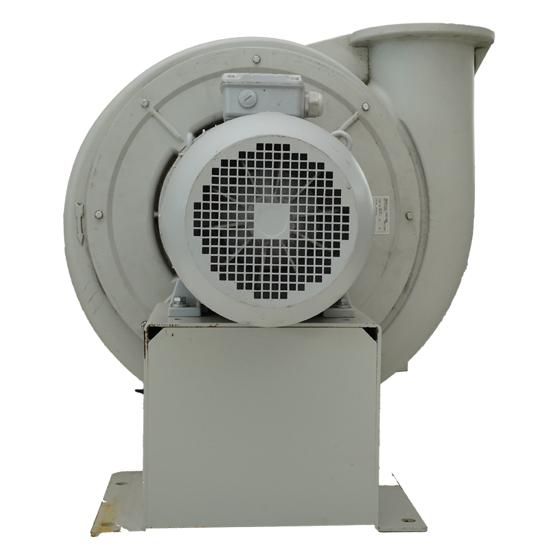
Structural featuresThe fan consists of impeller, casing, air inlet, transmission and other parts.
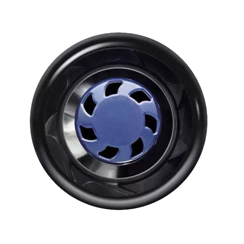
① Impeller – Made of Q345 (16Mn). There are 12 long and short blades with forward curved blades, which are evenly welded between the four arc-shaped wheel covers and the flat wheel disc, and the flow channel is equipped with a bladeless diffuser. The impeller is statically and dynamically balanced and runs smoothly and reliably.
② Casing – High-quality galvanized sheet is welded into a volute casing.
③ Air inlet – The air inlet is made into an integral structure with convergent and diffuser type, and is fixed to the front cover with bolts.
④ Transmission group – It consists of the main shaft, bearing box, coupling, etc. The main shaft is made of high-quality steel, the bearing box is an integral structure, and rolling bearings are used. The rolling bearings are lubricated with oil using a full-loss system.
PERFORMANCE & SELECTION PERFORMANCE & SELECTION
The performance of this fan is converted according to the fan characteristic curve without considering the compression correction factor.
1. The design and use unit shall determine the fan machine number, flow rate, wind pressure and matching motor in the performance and optional parts table according to the required flow rate and total pressure. If the motor specifications are changed, the speed and power shall be equivalent and indicated when ordering.
2. The operating point of each speed in the performance and optional parts table is the continuous pressure flow curve in the dimensionless characteristic curve of the fan within the range of total pressure efficiency greater than 83%, which is artificially divided into 11 performance points for selection according to the flow rate. The performance table shall prevail when ordering.
3. The factory inspection performance of the fan is that at the required flow rate, the deviation of the total pressure value does not exceed ±5% of the design total pressure value.
4. The performance and optional parts table is calculated according to the air medium under standard conditions when the gas temperature is t=20″C, the atmospheric pressure is p.=101300Pa, and the gas density is p=1.2kg/m³.
5. If the fan is not used under standard conditions, the performance should be converted according to the relevant formula.
6. In the performance and optional parts table:
![]()
(where p.q, η– fan flow (m³/h), total pressure (Pa) and air efficiency)
7. Mechanical efficiency of the fan, this series of fans are coupling transmission η1=0.98; K–motor capacity reserve coefficient, this fan takes 1.15. The motor power should generally not be lower than the required power value.