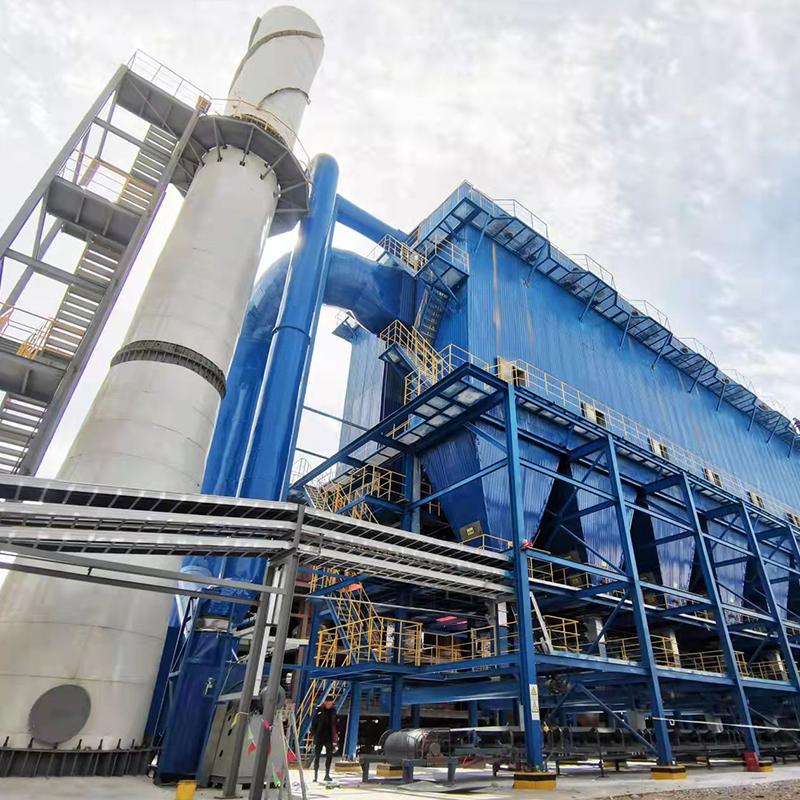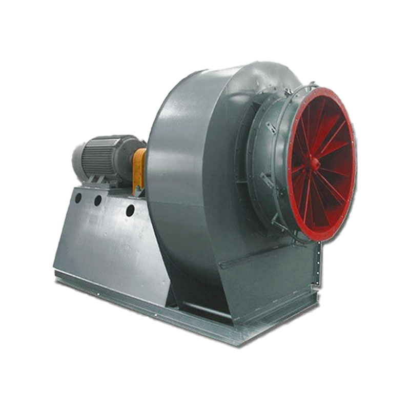
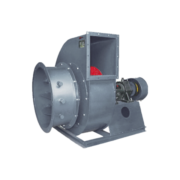

USES
G, Y6-51 boiler induced draft fans are mainly used for the induced draft system of 2t/h~670t/h steam boilers in thermal power plants, and also meet the requirements of high pressure head performance parameters of fluidized bed furnaces. This series of fans can also be used for dust removal, mine ventilation and general ventilation systems.
The medium conveyed by the induced draft fan is air, and the medium conveyed by the induced draft fan is flue gas or gas containing impurity particles. It can be used for more than four years when the impurity concentration is less than 200mg/m³. It can also be used if the impurity content is large, but the service life is relatively shortened. The maximum operating temperature of the induced draft fan shall not exceed 250℃.
TYPE
1. The fan and exhaust fan are usually made into single suction type. There are 20 machine numbers from 8D to 29.5D, with a total of 40 specifications.
2. Each fan can be made into two types: left-handed or right-handed. When viewed from one end of the motor, the fan with the impeller rotating in the clockwise direction is called a right-handed fan, represented by “right”, and vice versa, it is called a left-handed fan, represented by “left”.
3. The outlet position of the fan is represented by the outlet angle of the casing:
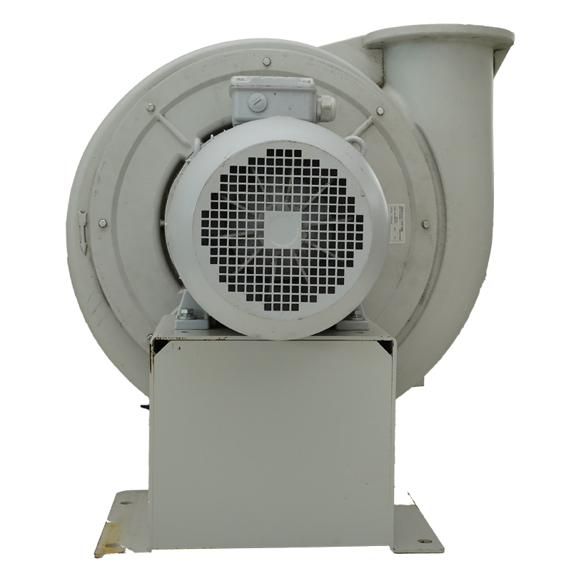
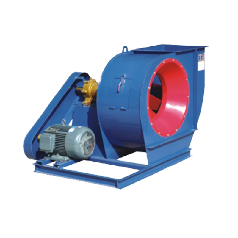
① The fan transmission mode is D type, that is, cantilever structure, and the motor and fan are connected by elastic coupling direct drive.
② The full name of the product is as follows: G6-51-1 № 18 D right 90°, Y6-51-1 № 18 D left 0°.
Among them, G and Y represent the boiler forced draft fan and boiler induced draft fan respectively, 6 is the pressure coefficient of the highest efficiency point rounded to 10, 51 is the specific speed, 1 is the first design, No. 18 means the impeller diameter is 1800 mm, and 90° is the outlet angle.
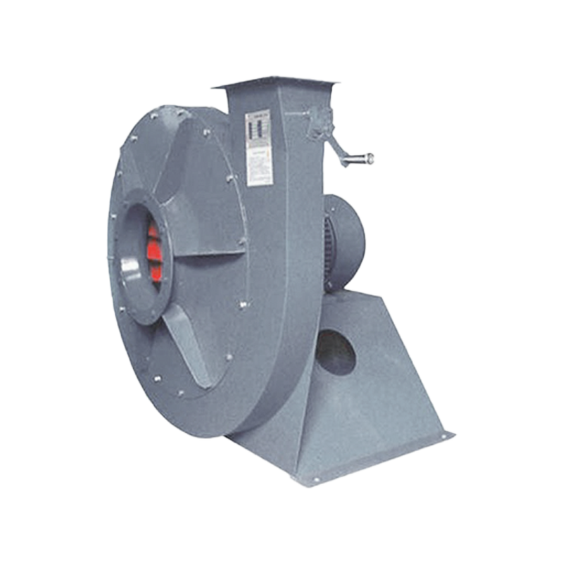
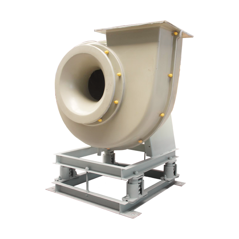
STRUCTURAL FEATURES
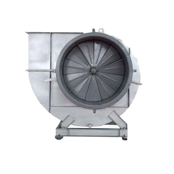
1. The design of this series of fans is based on the aerodynamic outline finalized after more than one year of model testing and adopts the patented technology of “adjustable air inlet”; high-strength wear-resistant impeller, oil-leakage-proof bearing box, self-aligning axial adjustment door and other advanced proprietary technical achievements.
2. High-strength wear-resistant impeller: The impeller adopts a close-diameter, backward single-plate blade to reduce airflow impact, good stability, and the motor is not easy to overload. It overcomes the undesirable phenomena of internal dust entry and non-working area dust causing vibration after the original 4-73 type wing-shaped hollow blade is worn through. The wear-prone parts of the induced draft fan blades are welded with wear-resistant welding dedicated to the fan, which greatly extends the service life of the fan. This type of fan has a high pressure coefficient, low peripheral speed, and low noise, so it is practical.
3. Anti-leakage bearing box: The overlapping oil-slinging ring is used to throw the oil brought by the high-speed rotating bearing to the inner wall of the bearing box and flow back to the oil pool; the semi-open aluminum oil seal can increase the resistance along the axial direction to intercept part of the thin oil back to the oil pool in addition to facilitating maintenance and preventing friction accidents; the external pressure packing is to block a small amount of thin oil; the upper part of the bearing box is equipped with a vent plug to reduce the slight positive pressure in the bearing box, ensuring no oil leakage and good dustproof performance.
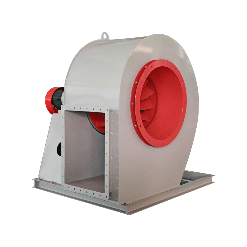
4. Self-aligning axial adjustment door: The guide vane fulcrum of the adjustment door is equipped with a self-aligning bearing, and there is no “dead” point during operation and adjustment, so the adjustment is flexible and labor-saving, safe and reliable, ensuring that the actuator is not overloaded, and can also be used outdoors.
5. The fan is assembled in one piece or in two parts: the transmission group, motor and coupling cover of the fan No. 16 D or below are assembled on a complete base before leaving the factory; the casing, air inlet and regulating door are another base. The small-sized fan is assembled on two bases before leaving the factory, and the large-sized fan is disassembled and assembled on three bases (its motor is another base). 6. The fan is easy to install and repair: the fan has two complete bases, the casing and the transmission group. The casing is equipped with a center dividing surface or a vertical dividing surface, which is particularly convenient for disassembly and assembly; the rotor can be lifted vertically, and it can also be disassembled axially if only the impeller is replaced.
7. Key measures to ensure product quality:
① When the impeller diameter of the fan is greater than 2 m or the peripheral speed exceeds 100 m/s, non-destructive testing is carried out according to the standard.
② When the impeller peripheral speed is high, reinforced blades are used, and the wear-resistant welding rods dedicated to the fan are used for the wear-resistant parts of the induced draft fan blades. After on-site wear, users can weld by themselves.
③ The fan inlet and outlet are equipped with soft connection belts to prevent stress interference caused by deformation of the pipe and fan.
④ SKF imported rolling bearings are used for fans of №14 D ~29.5 D.
⑤ Vibration protection devices are installed above №16 D to prevent damage to the unit due to vibration.