
USES
G and Y4-68 boiler centrifugal draft fans are a series of products jointly designed by the fan industry in 1982. They are mainly suitable for the draft and induced draft systems of steam boilers with an evaporation capacity of less than 230t/h in thermal power plants. When the performance is similar and there are no special requirements, G4-68 can also be used for mine ventilation and general ventilation. Both types of fans have the advantages of high efficiency, low noise and high strength.
The medium conveyed by the fan is air, and the maximum temperature shall not exceed 80℃. The medium conveyed by the induced draft fan is flue gas, and the maximum temperature shall not exceed 250℃.
Before the induced draft fan, a dust removal device with a dust removal efficiency of not less than 85% must be installed to reduce the dust content of the flue gas entering the fan and increase the service life of the fan.
FORM
1. Both the ventilator and the induced draft fan are made into single suction, each with 7 numbers from No.8 to 16.
2. Each fan can be made into two forms of right-hand rotation or left-hand rotation. Looking at the fan from one end of the motor, the impeller rotating in the clockwise direction is called a right-hand fan, represented by “right”; the impeller rotating counterclockwise is called a left-hand fan, represented by “left”.
3. The outlet position of the fan is represented by the outlet angle of the casing. Both “right” and “left” fans can be made into 6 angles: 0°, 45°, 90°, 135°, 180°, and 225°.
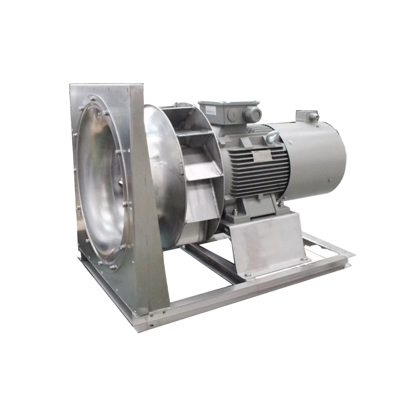
4. The transmission mode of the fan is D type, and the motor and the fan are connected by elastic coupling direct drive.
5. The full name of the product is as follows: “GY4-68No.8D right 90”, where G and Y represent boiler ventilator and boiler induced draft fan respectively.
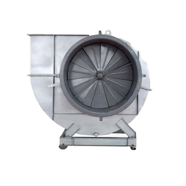
STRUCTURAL FEATURES
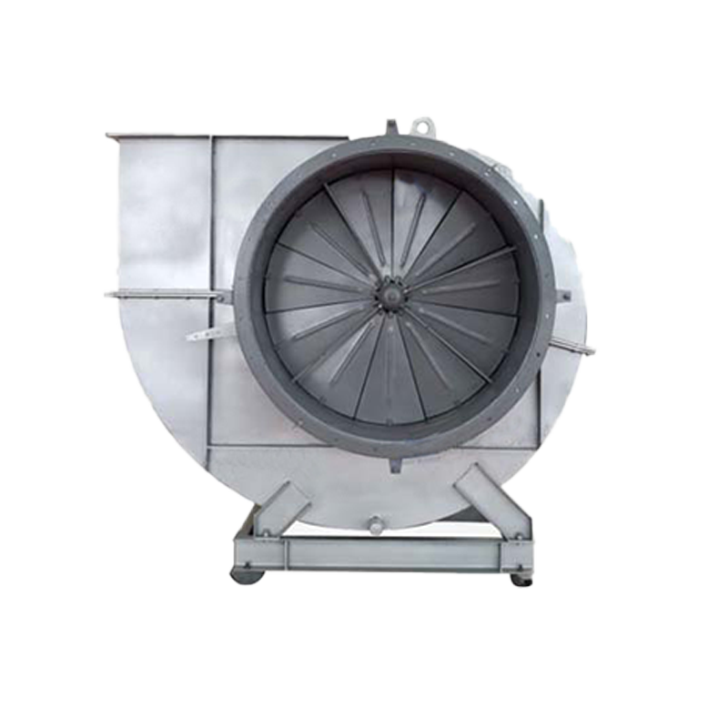
① Impeller – Made of 12 backward-inclined wing-shaped blades welded between the arc-conical wheel cover and the flat wheel disc. The impeller of the induced draft fan is generally 16Mn, and a wear-resistant guard plate is lined at the intersection of the blade and the wheel cover. The blade head is solid, and wear-resistant materials are added to the wear-prone part to increase the service life of the blade, which is different from the ventilator. The impellers have been subjected to static and dynamic balance correction and overspeed operation experiments, so the operation is stable and reliable.
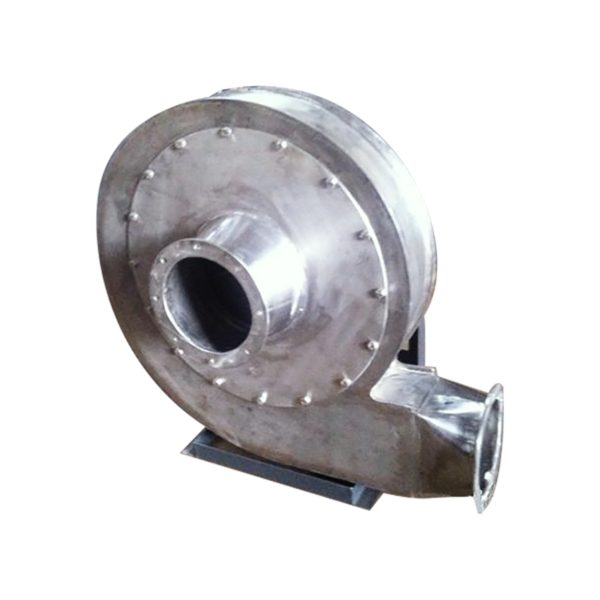
② Casing – A volute body welded with ordinary steel plates. The casing of the single-intake fan is made into two different forms: the casing of No. 8 to No. 12.5 is made into an integral structure, and a quarter of the casing of No. 14 and No. 16 can be removed. For the induced draft fan, the volute plate has an ash removal door and is appropriately thickened to prevent soot wear.
③ Air inlet – a convergent streamlined integral structure, fixed to the side of the casing inlet with bolts.
④ Used to adjust the fan flow. №8 and №12.5 are composed of 11 petal-shaped blades, and №14 and №16 are composed of 13 petal-shaped blades. They are all axially installed in front of the air inlet. Due to the external transmission structure, the rotation is flexible and convenient, and the adjustment range is from 90 (° fully closed) to 0 (° fully open). The position of the adjustment door lever is on the right side from the air inlet direction. For right-handed fans, the lever is pushed from bottom to top from fully closed to fully open; for left-handed fans, the lever is pulled from top to bottom from fully closed to fully open. In order to ensure the normal operation of all parts of the adjustment door, lubrication must be paid attention to. For the adjustment door of the fan, calcium-sodium based grease is used for lubrication; for the induced draft fan, due to the high gas temperature, molybdenum disulfide high-temperature (260℃) grease must be used for lubrication.
⑤ Transmission group—The transmission mode is D type. It consists of a main shaft, a bearing box, a coupling, etc. The main shaft is made of high-quality steel. The rolling bearing water-cooled integral bearing box is adopted. Therefore, a water pipe needs to be installed. The water consumption varies with the ambient temperature, and is generally considered to be 0.5~1m³/h. The bearing box is equipped with a thermometer and an oil level indicator. The lubricating oil adopts the full loss system oil L-AN46, and the amount of oil added is in accordance with the requirements of the oil level mark.
PERATION
If the operation is good, then switch to full load (specified full pressure and flow) operation
① Full load operation, for a newly installed fan, not less than 2 hours, for a repaired fan, not less than half an hour.
② After the fan is started, gradually open the adjustment door until it reaches normal operating conditions. During operation, the bearing temperature rise shall not exceed 40℃ above the ambient temperature. The root mean square vibration velocity value of the bearing part shall not exceed 6.3 mm/s.