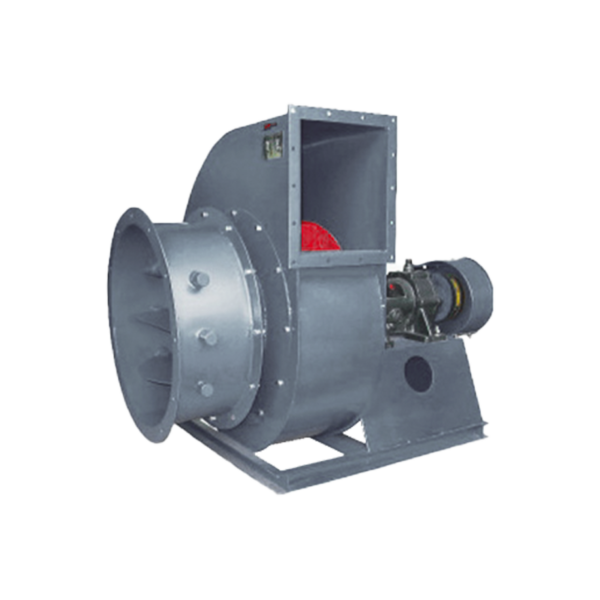
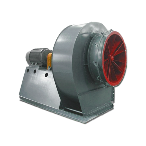

USES
Y5-48 boiler centrifugal induced draft fan is designed to match 1~20th industrial boilers burning various coal qualities and equipped with smoke and dust removal devices. It can be selected with similar air intake conditions and suitable performance. The maximum temperature shall not exceed 250°C. A dust removal device with an efficiency of not less than 85% must be installed in front of the induced draft fan to reduce the dust content of the flue gas entering the fan, so as to increase the life of the fan.
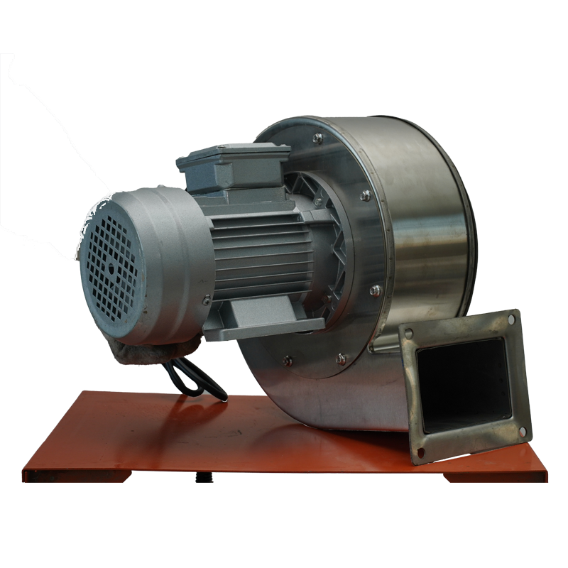
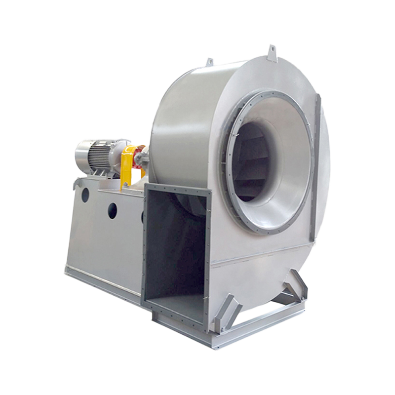
FORM
The induced draft fan is made of single suction. The machine numbers are No.4, 5, 6.3, 8, 10, and 12.5. The six induced draft fans can be made into right-handed or left-handed. Looking at the fan from one end of the motor, if the impeller rotates clockwise, it is called a right-handed fan, represented by “right”; if the impeller rotates counterclockwise, it is called a left-handed fan, represented by “left”. The outlet position of the fan is represented by the outlet angle of the fan housing. Both “left” and “right” can be made into six angles: 0°, 45°, 90°, 135°, 180°, and 225°.
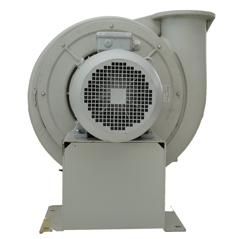
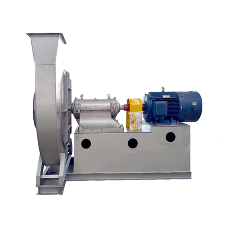
STRUCTURALFEATURES
Structural features At present, there are many series of industrial boilers, and the quality of the coal used is very different. The resistance of the dust collectors used is different, and the air volume and air pressure of the required induced draft fans vary greatly. In order to adapt to the above situation, considering the economy of the fan, V-belt (C-type) transmission is adopted. In this way, not only can different speeds be used with one machine number to meet the requirements of various dust collectors for the same tonnage boiler, reducing the series and machine number of the fan, but also it is convenient for the user to choose different speeds according to the actual situation to obtain the required ideal air volume and air pressure.
① The impeller has 12 backward inclined flat blades, made of Q345 (16Mn), welded between the arc-conical wheel cover and the flat wheel disc, and corrected by static and dynamic balance, so it runs smoothly and has high strength.
② Casing -No.8 and above “left” and “right” are universal. There is also a dust cleaning door on the volute to facilitate the removal of dust accumulated on the blades and in the casing, ensuring the balance and aerodynamic performance of the impeller.
③) The air inlet-air inlet is made into a convergent streamlined overall structure and is fixed to the inlet side of the casing with bolts.
④ The blades of the regulating door are petal-shaped, No. 4~6.3 are 9 pieces, and No. 8 and above are 11 pieces. Axially installed in front of the air inlet. Due to the use of an external transmission structure, the rotation is flexible and convenient, and the adjustment range is from 0° (fully open) to 90° (fully closed). The position of the handle of the regulating door is on the right side from the direction of the air inlet. For the “right” cyclone, pushing the handle from bottom to top is from fully closed to fully open; for the “left” cyclone, pulling the handle from top to bottom is from fully closed to fully open. In order for the various parts of the regulating door to work properly, they must be well lubricated. The lubricating grease uses molybdenum disulfide high temperature (260°C) grease, which can ensure lubrication when the fan is running at high temperature.
⑤The transmission group consists of the main shaft, bearing box, pulley, etc. The main shaft is made of high-quality steel and uses ball bearings and water-cooled integral bearing boxes. Therefore, a water pipe must be installed. The water consumption varies with the ambient temperature, generally considered to be 0.5~1m/h. The bearing box is equipped with a thermometer and an oil level indicator. It uses full-loss system oil L-AN46 for lubrication, and the amount of oil added is based on the requirements of the oil level mark.
OPERATION
After all installations are completed and the general inspection is passed, the test run can be carried out. In order to prevent the motor from being overloaded and burned, the fan must be started and tested without load (i.e. the gate or regulating door in the air intake duct is closed). If the situation is normal, then the regulating door is gradually opened for a full-load continuous operation test. The test run time of the newly installed fan is not less than 2 hours, and the test run time of the repaired fan is not less than half an hour. If there is no abnormality, it can be officially used. The current should be strictly controlled during operation and must not exceed the standard.
Check the spacing of each part of the fan, whether there is any scratching or even collision between the rotating part and the fixed part, and whether the oil level of the bearing box is between the minimum and maximum oil levels. Check whether the electrical circuit and instrument are correct, and check whether the cooling part is normal. Close the regulating door.
Start the machine and check for any abnormalities. If there are no abnormalities, gradually extend the start-up time until the normal speed is reached. After reaching the normal speed, gradually open the adjustment door until the specified load is reached. When there are no special requirements for the bearing temperature, the bearing temperature rise shall not exceed 40℃ of the ambient temperature, and the root mean square vibration velocity value of the bearing part shall not exceed 6.3mm/s. If the fan is found to have severe vibration, impact, rapid increase in bearing temperature and other abnormal phenomena, it must be stopped immediately to find out the cause.