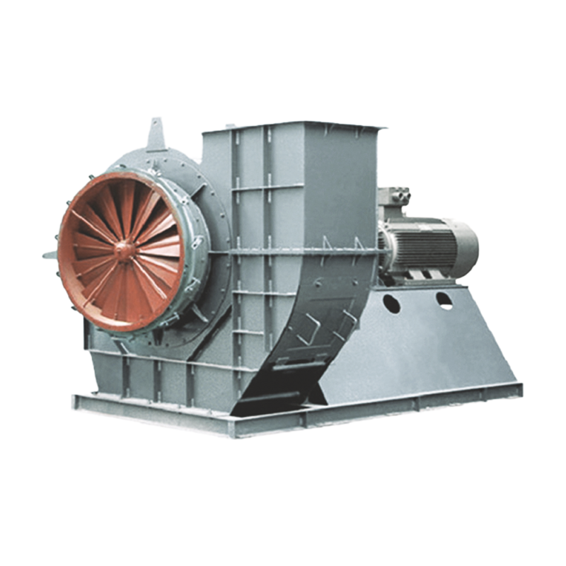

USES
Y8-39 and Y9-38 series of centrifugal induced draft fans for industrial boilers are designed to enable the induced draft fan to work in the high-efficiency zone when the industrial boiler is running under variable conditions, so as to achieve the purpose of energy saving. The fan energy-saving group of the Ministry of Machinery Industry organized the national fan industry experts to jointly design and promote the high-efficiency energy-saving products with the advantages of high efficiency, low noise and wide performance curve high-efficiency zone.
This fan is suitable for 0.5~35t/h industrial boilers equipped with economizer (preheater) and smoke and dust removal devices. All those with similar air intake conditions and suitable performance can be selected, but the maximum air intake temperature shall not exceed 250℃. A dust removal device with a dust removal efficiency of not less than 85% must be installed in front of the induced draft fan to reduce the dust content of the flue gas entering the fan, reduce the wear of the fan by the smoke and dust, and increase the service life of the fan.
TYPE
1. This fan is made of single suction. The machine numbers are 4, 4.5, 5, 5.6, 6.3, 7.1, 8, 9, 10, 11.2, 12.5, 14, 16.
2. This fan can be made into two forms of clockwise rotation and counterclockwise rotation. Looking at the fan from the transmission part, if the impeller rotates clockwise, it is called a right-handed fan, represented by right, and vice versa, it is called a left-handed fan, represented by left.
3. The outlet position of the fan is represented by the outlet angle of the casing. Both right-handed and left-handed fans can be made into six angles of 0°, 45°, 90°, 135°, 180°, and 225°. If you need other machine numbers or other angles, our factory has the strength to design and manufacture for you “order dishes” until you are satisfied.
CHARACTERISTICS
There are many series of industrial boilers at present, and the quality of coal used varies greatly. The resistance of the dust collector and economizer used is different, and the air volume and air pressure of the required induced draft fan vary greatly. Considering the economy and adaptability of the fan, two series of fans, Y8-39 and Y9-38, are provided for users to choose. The connection and installation dimensions of the two series of fans with the same machine number are the same.
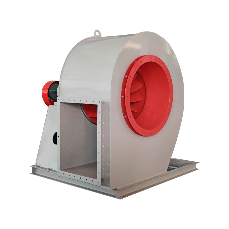
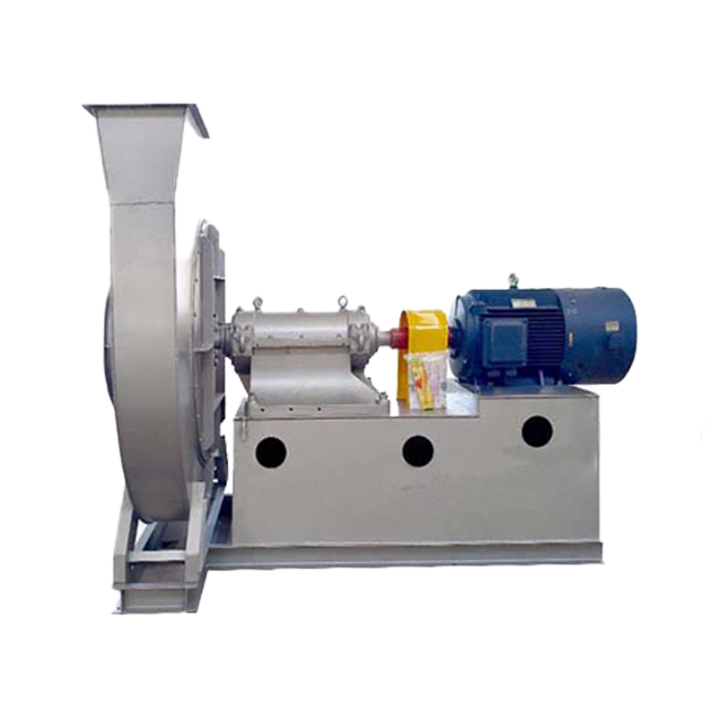
STRUCTURAL FEATURES
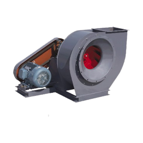
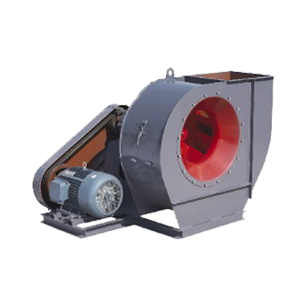
The fan consists of impeller, casing, air inlet, transmission group, regulating door and other components.
① Impeller – Made of 16Mn, with long and short forward curved blades, welded between the arc-conical front disk and the flat rear disk. After the impeller is formed, it undergoes strict static and dynamic balance correction and overspeed operation test, so it runs smoothly and reliably.
② Casing – Welded into a volute shape with high-quality galvanized sheet. There is a dust cleaning door on the volute to facilitate the removal of dust accumulated in the blades and casing.
③ Air inlet – Made into a convergent streamlined overall structure, fixed to one side of the fan with bolts.
④ Transmission group – Consists of main shaft, water-cooled bearing box, and coupling.
The main shaft is made of high-quality steel and uses rolling bearings. The bearing box has two types: integral and split. №4~6.3 use integral bearing box; №7.1~16 use split bearing box. Both bearing boxes need water cooling. The water consumption varies according to the working temperature and ambient temperature. Generally, it is considered to be 0.5 m3/h ~1m3/h. The bearing box is equipped with a thermometer and oil level indicator. The bearing box uses No. 30 mechanical oil. The oil filling amount is implemented according to the requirements of the oil mark.
⑤ Adjustment door – used to adjust the fan flow. The adjustment door is a petal-shaped centering type, axially installed before the air inlet, and adopts an external transmission structure. It is flexible and convenient to rotate, and the adjustment range is from 90° (fully closed) to 0° (fully open). The position of the plate handle of the adjustment door is on the right side from the air inlet direction. For right-hand rotating fans, pushing the handle from bottom to top is from fully closed to fully open; for left-hand rotating fans, pulling the plate handle from top to bottom is from fully closed to fully open. In order to ensure the normal operation of the regulating door, good lubrication is required. It is recommended to use high temperature (260℃) bentonite grease to prevent the fan from failing when running at high temperature. A dust removal device with a dust removal efficiency of not less than 85% must be installed to reduce the dust content of the flue gas entering the fan, reduce the wear of the fan by the smoke and dust, and increase the service life of the fan.